Kubernetes Networking #1
2022-01-10
Kubernetes networking can be a bit of a rabbit hole to debug and discover what your pods are actually doing. In this post we’ll explore at a high level how a request goes from 1 pod to another and which components control each.
Components
The components we’re going to look at today are:
kube-dns/corednsresolves domain names for services (and pods) into an IP address- ℹ️
kube-dnswas replaced bycorednsbut the in cluster service is still calledkube-dns - This is the resolver for any DNS requests inside your pods, if you wanted to resolve internal service domains or to a private DNS resolver, you could configure this to forward those requests.
- ℹ️
kube-proxyresolves network requests for the IP address of a service to the IP addresses of pods which match that service. This has different modes:- Your chosen CNI, there’s a range of these, all which work differently. Generally a CNI will configure any networking around a Pod IP, routing to and from pods to:
- Ensure pod network requests are routed properly to other pods
- Ensure pod network requests can reach outside the cluster
An easy way of thinking about it can be, resolving between a service and healthy pods is kube-dns and kube-proxy but then that request will need to go through routing setup by the CNI. For cloud environments, your CNI will usually handle (or provide ways to setup) things like cross-subnet traffic as well.
To follow the resolution between components, say we wanted to go to a service called myapp which sits in namespace namespace001 which had 2 healthy pods matching the service selector. The resolution would be:
- CoreDNS: (service FQDN)
myapp.namespace001.svc.cluster.local→172.16.10.10(service cluster IP) - iptables:
172.16.10.10→10.10.10.10(a pod IP, selected at random from healthy pods) - CNI: Will route traffic for
10.10.10.10from the requester node, to the target node
Example journey of a request
As an example, let’s explore in an example Kubernetes cluster how a pod will send a network request to another pod. For this example:
- The pod will try to talk to a pod on another node then itself
- The 2 nodes will be in seperate subnets
- Routing between subnets is presumed to be setup and fine and we’ll abstract that to a
routerin the diagram
- Routing between subnets is presumed to be setup and fine and we’ll abstract that to a
- The
CNIwill be Calico, but we won’t be looking too much into its internals - pod-0 will send a request to pod-3 through a service
- We’ll assume Kubernetes and Calico are setup with defaults:
- iptables mode for
kube-proxy - vxlan encapsulation for cross subnet traffic
- iptables mode for
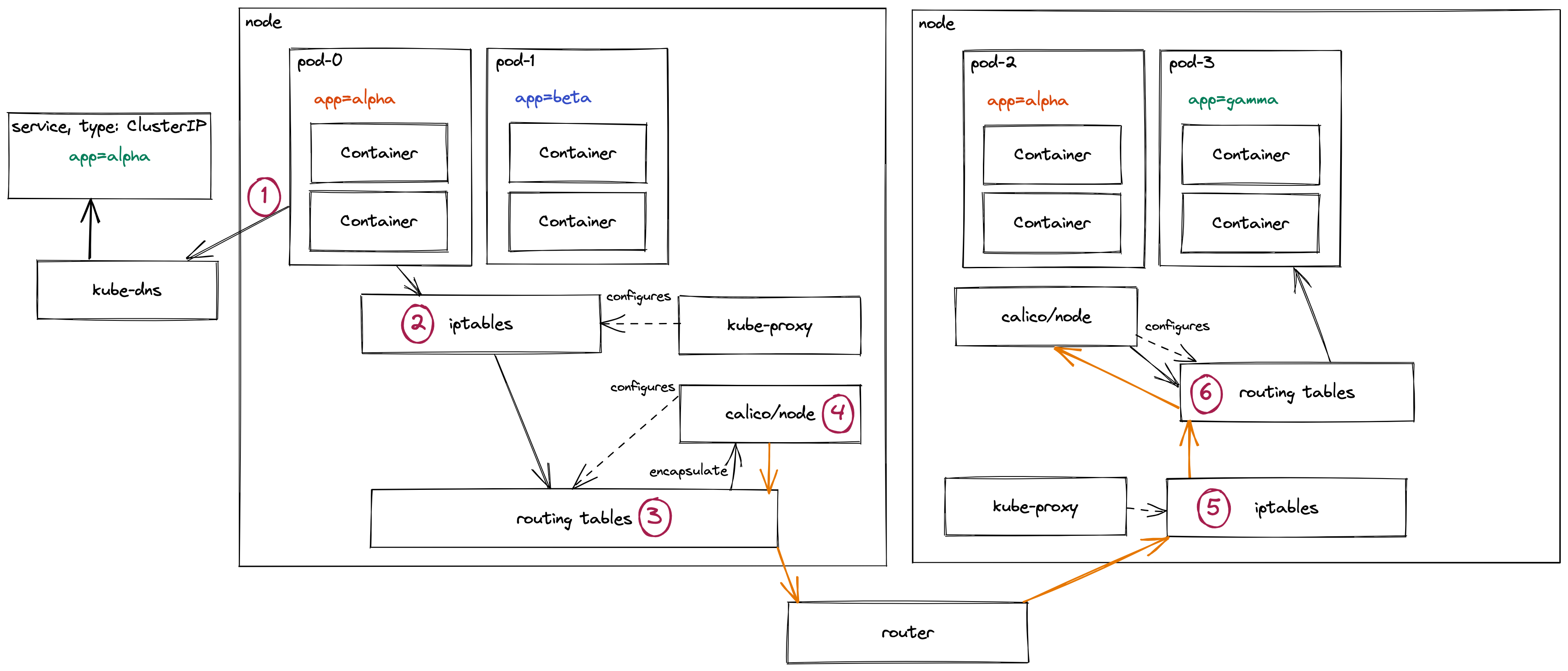
-
1 pod-0 requests the service’s Cluster IP from
kube-dnskube-dnshas dynamic config which updates mapping the service name to a Service IP address lets say172.16.10.10- `kubectl exec command for coredns
- *technically this whole request to
kube-dnsgoes via the same iptables→routing tables path sincekube-dnsruns in pods on the cluster. The only key difference is the DNS resolver is an IP address so it doesn’t askkube-dnsto definekube-dns. But trying to show aswell would be madness.
-
2 With the cluster IP (
172.16.10.10) the request hits iptables- iptables selects from a random one of the pod IP addresses for this particular service IP
iptables -Loriptables-save
- These rules are all loaded in here and dynamically updated by `kube-proxy If a pod starts failing Readiness checks for instance, it gets removed from this list.
- iptables selects from a random one of the pod IP addresses for this particular service IP
-
3 The Pod IP is now resolved in the nodes routing tables
sudo route -norip route list- These routing table rules will be configured based on the network environment the node sits in. Calico, running locally, will also configure rules for pod networking.
- Based on the Pod IP, it’ll be resolved through multiple sets of rules:
- This node will have a range of Pod IPs which resolve to the local node itself
- This node will also have an IP range for nodes inside the same subnet - these could avoid encapsulation for performance gain
- This node also has range(s) for other subnets, if it’s not local to the node or subnet, it then gets routed to the subnet routing table. For these rules, Calico might instead route traffic to itself to be encapsulated before crossing the network boundary.
- There also might be a range for external traffic not local to the network, but if this was a private subnet this is most likely behind a NAT gateway inside the local network
- This particular request is destined for another subnet. The routing table has directed the request to the Calico pod running locally on this node to handle routing this.
-
4 Calico will now encapsulate the network request to allow it to pass subnet boundaries
calicoctl node status- By encapsulating the request’s original networking information is wrapped up as data and new network info is added
- Calico will send this as a vxlan or ipinip packet to the required node in another subnet
- The encapsulated packet (shown as an orange line) will:
- Go back through the route table on the node itself
- To the local subnet router, which will resolve which subnet it needs to go into
- Hit the destination subnet routing table which can direct it to the node
- To the other node itself
-
5 Once the encapsulted packet arrived at the other node, it’ll go through iptables rules to see if it’s allowed traffic.
- This is why you might need to add the encapsulated packets into your firewall rules to be allowed in.
-
6 The routing table on this node will now:
- Send the encapsulated packet to the local Calico to be unencapsulated
- The original (unencapsulated) network request will resolve again in iptables and routing tables rules to determine where it should go
- This could also cause the packet to have to be routed again since the destination has moved
- The request is directed to the pod running locally
There are a lot of things missed off here:
- Technically iptables is interacted with before, after (and sometimes during) a routing decision
- How the pod sits within it’s own network namespace with a virtual ethernet interface for traffic coming to the pod
- How Calico uses Felix to program it’s routes and ACLs and BIRD for distributing the routes to BGP peers on the network
- Alternate CNIs
- How the whole kube-proxy aspects could be stipped out for an eBPF approach (Calico’s eBPF dataplane or Cilium and it’s kube proxy replacement)